DC & AC Magnetic Field Mitigation Challenges & Solutions for High-Resolution Transmission Electron Microscopes
Transmission electron microscopes (TEM) with tight magnetic field specifications pose a significant challenge for magnetic field mitigation and active magnetic field cancellation because of the length of the electron beam column. Unlike a scanning electron microscope (SEM), focused ion beam instrument (FIB), or a dual beam, with relatively short columns of ~1-2 feet, the column of TEMs is much longer with sensitivity to magnetic fields at the top of the microscope at the source and at the bottom near the detector. Room shielding is always an option, but this can be very expensive and add significant time to a project schedule. Also, the standard 1/4″ aluminum shielding is only effective for AC, not DC fields. So, even in a shielded room, a DC magnetic field cancellation system is required to mitigate the DC component of the magnetic field interference.
This article outlines the strategies for magnetic field mitigation for TEMs, and it describes why a dual cancellation system is the most appropriate active magnetic field cancellation strategy for very high-resolution TEMs with extremely tight specifications.
An Overview of Magnetic Field Cancellation Systems
Magnetic field cancellation systems optimize field cancellation for a single point.
Generally, two factors impact how a magnetic field cancellation system functions:
- Cable Layout: The layout of cables determines the field uniformity of cancellation.
- Sensor Position: The sensor’s position is crucial, as it is the point in space where magnetic field cancellation is optimized.
A single cancellation system works well for most SEMs, FIBs, and Dual Beams with short electron beam columns. In such cases, VEC will design the cable layout for adequate and generally uniform cancellation performance and position the sensor to optimize performance at critical locations.
The Challenge of High-Resolution TEMs
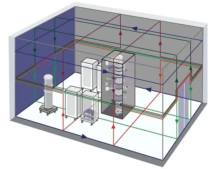
However, TEMs with long columns present challenges. A single-cancellation system setup strategy involves arranging the cable layout to achieve uniform cancellation along the electron beam column, often using a dual-loop configuration. VEC then places the sensors at the center of the column for optimized cancellation.
This strategy has shortcomings in two scenarios:
- High Field Gradient: When there is a significant gradient in magnetic fields between the top and bottom of the microscope, optimizing cancellation at the center results in over-canceling at one end and under-canceling at the other.
- Tight Specifications: When specifications are very tight, any variation or gradient in the field becomes challenging to manage, especially in the 20-10 nanoTesla peak-to-peak range.
Example
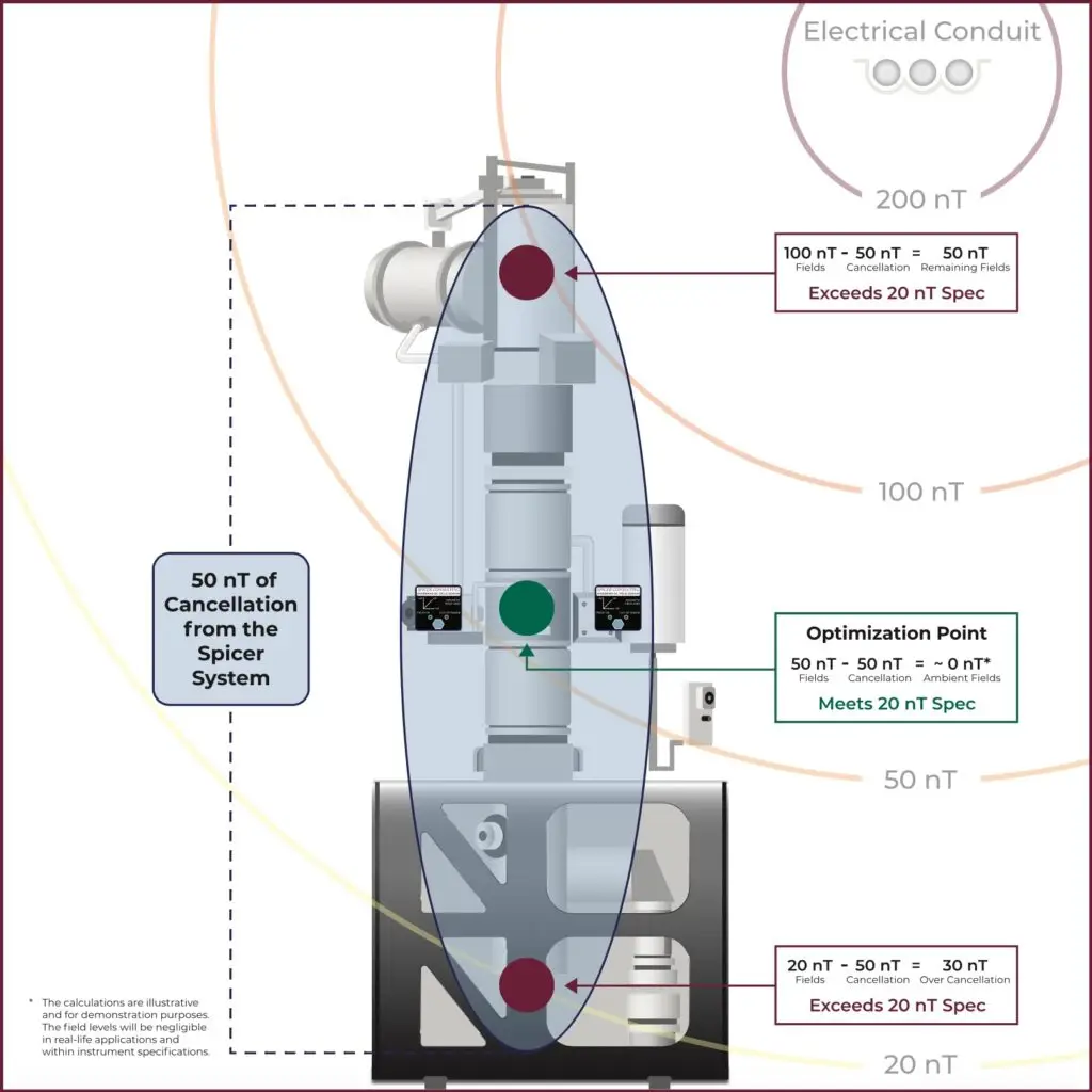
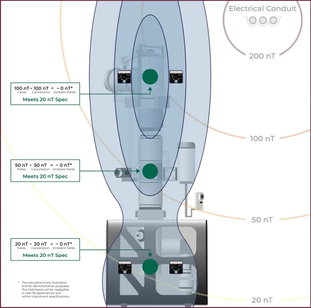
Consider a scenario with an overhead conduit or EMI sources, resulting in a field gradient with a 100 nanoTesla field at the top of the microscope and 20 nanoTesla field levels at the bottom near the detectors. Even if a single system is optimized to cancel the field at the center, it results in under-cancellation at the top and over-cancellation at the bottom. The single cancellation point at the center of the microscope poses a challenge, as bringing both the source and detector levels within specification becomes problematic if the field gradient is within specifications. In this scenario, the best that a single-cancellation system can achieve is 50 nT at the source and 30 nT at the detector level, exceeding the microscope’s specifications.
Shielding, How it Works, & Considerations
With the tight specifications, instrument costs, and operational importance of high-resolution TEMs, customers often go to great lengths to protect their TEMs from electromagnetic interference. One way to do this is through room shielding. Below, we will describe different shielding techniques, their physical principles, and considerations for their application.
Eddy Current Shielding - AC Magnetic Fields
Typically Aluminum
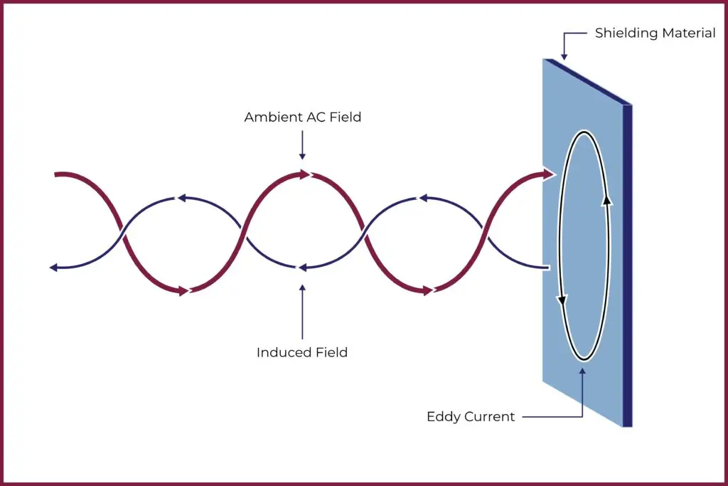
Eddy current shielding mitigates the effects of magnetic fields by inducing opposing currents within a conductive material. This method operates on the principle of Lenz’s law, where the magnetic field generated by these induced currents counteracts the external magnetic field. When exposed to varying magnetic fields, materials like copper, aluminum, or other conductive alloys create eddy currents. These currents produce secondary magnetic fields that oppose the primary field’s influence, reducing its strength within the shielded region. The effectiveness of eddy current shielding depends on several factors, including material selection, thickness, and design configuration. Electron microscopy labs typically use 1/4″ seam welded aluminum on all four walls, ceiling, and floors with careful consideration for mechanical, electrical, and plumbing considerations. Contractors usually install the aluminum behind the finished walls, floor, and ceiling, requiring a complete room renovation.
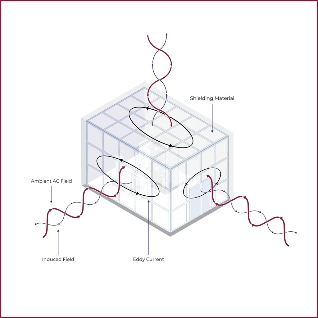
Aluminum is effective for shielding against AC magnetic fields primarily due to its high electrical conductivity. When exposed to AC magnetic fields, aluminum quickly develops eddy currents, creating magnetic fields that oppose the external field and thus attenuate it. However, aluminum’s effectiveness as a shielding material diminishes for DC or slow-moving magnetic fields because DC fields do not induce significant eddy currents.
Flux Shunting - DC +AC Magnetic Fields
Typically, Silicon Iron or Mu-Metal
Shielding against DC magnetic fields requires materials with high magnetic permeability, such as certain nickel, iron, or cobalt alloys. These materials possess properties that effectively redirect and absorb magnetic flux lines. Choosing the appropriate material and thickness is crucial when designing a shield for DC magnetic fields. Thicker layers of high-permeability metals provide higher levels of magnetic field attenuation. Additionally, shaping the shield to enclose the target area enhances shielding effectiveness by redirecting the magnetic flux around the protected space.
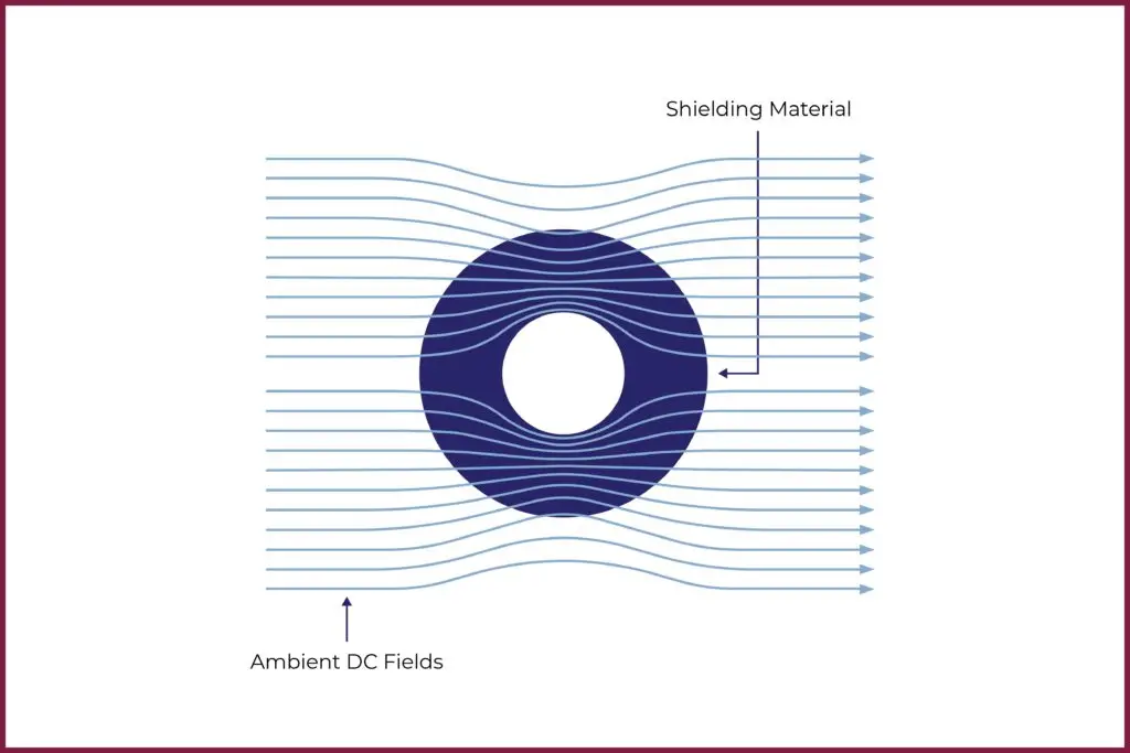
Furthermore, the contractor must carefully seal and shield the joints in the shielding material to prevent magnetic field leakage and maintain continuity. Any gaps or imperfections can allow magnetic flux to penetrate the shield, reducing its effectiveness. Moreover, the contractor must consider the orientation of the shielding material in relation to the magnetic field direction, as this can impact shielding efficiency. By aligning the shield’s material with the direction of the magnetic field, it can maximize its ability to redirect and absorb the magnetic flux. Overall, shielding against DC magnetic fields with high-permeability metals requires attention to material selection, thickness, configuration, and installation details to ensure effective containment and protection of sensitive equipment or environments from the effects of magnetic fields.
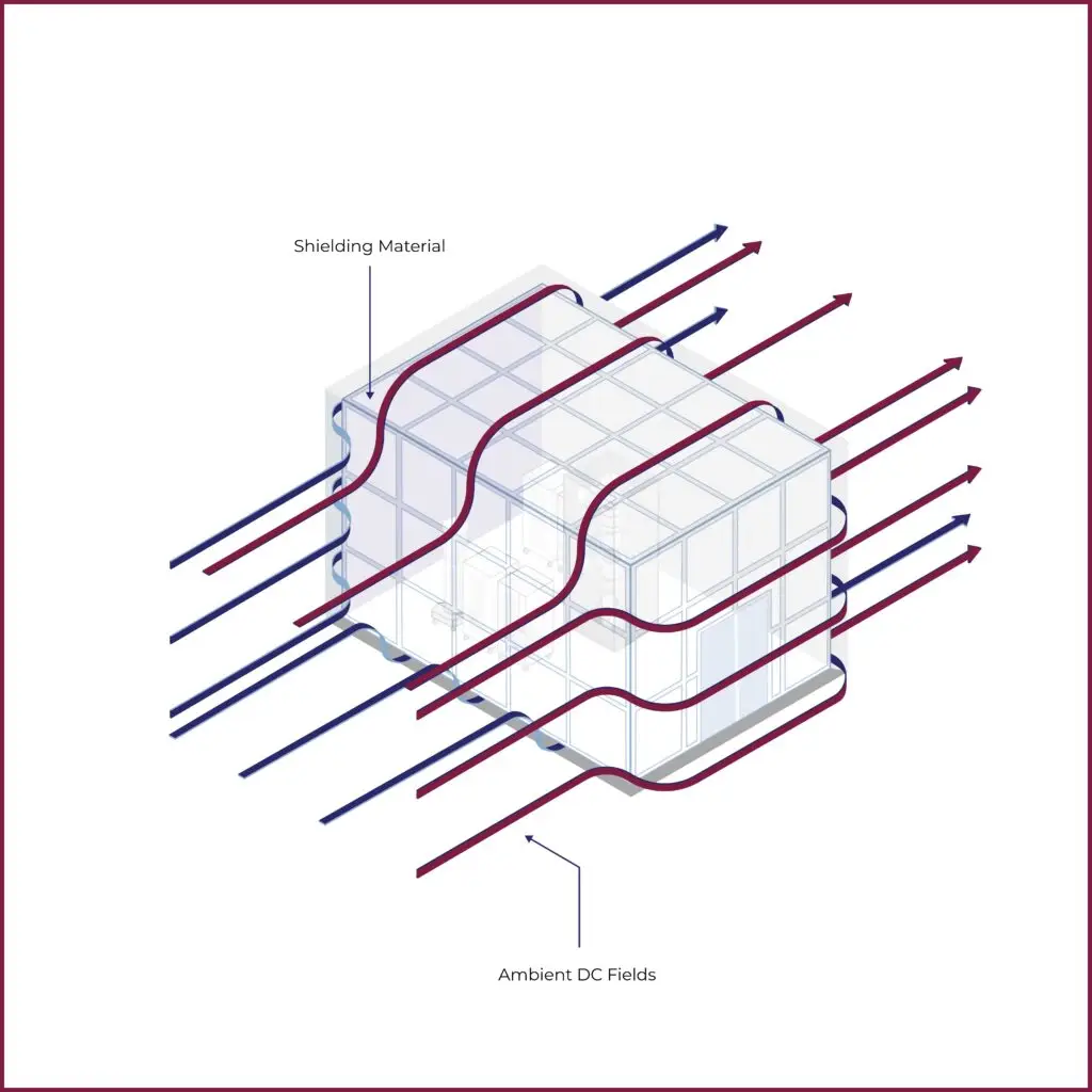
Although effective, mu-metal, with its high permeability and nickel content, is expensive and often has long lead times. Another option involves multiple layers of silicon iron shielding, which is cheaper and more available but is less effective.
The Dual Cancellation System Solution
In many situations with field gradients in TEM rooms, VEC proposes a dual cancellation system that employs two independent cancellation systems to address these issues. VEC optimizes one cancellation system for the top of the microscope near the source and the second near the bottom of the microscope near the image filter. This system accommodates field gradients in the room by canceling different amounts of field at the top and bottom of the microscope, addressing the challenges of dramatic field gradients.
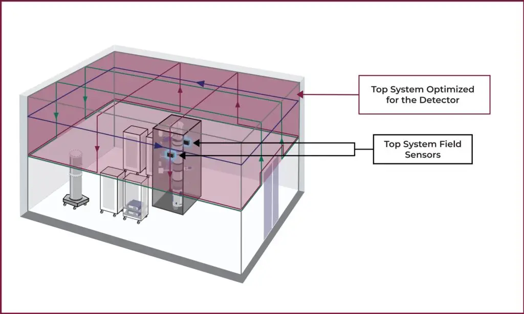
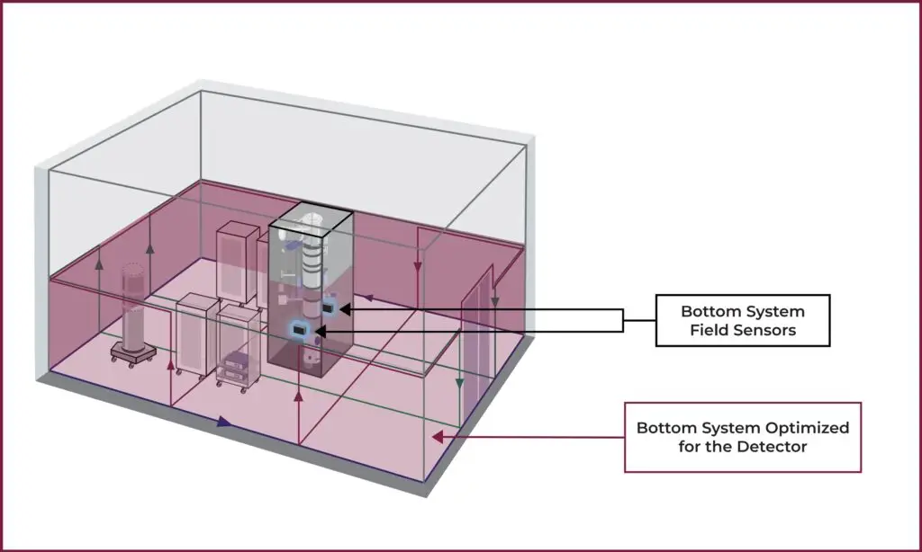
Let us return to our example of the TEM with an overhead electrical conduit. With a Dual Cancellation System, VEC could optimize and cancel the higher fields at the top of the microscope and optimize and cancel a second system at the lower field levels at the bottom, bringing the entire electron beam column into specification. The image below shows that the two systems work together to produce a canceling field that changes smoothly between 100 nT at the top and 20 nT at the bottom.
Dual Cancellation System with Virtual Sensor
Since magnetic field cancellation systems optimize cancellation for a single point, it is physically impossible to place the sensor in the optimal location, in the center of the electron beam column, while the microscope operates. The virtual sensor addresses this problem. The Spicer magnetic field cancellation systems allow for a virtual sensor setup where the controller mixes data from two magnetic sensors to move the cancellation point to the center of the column where it matters the most.
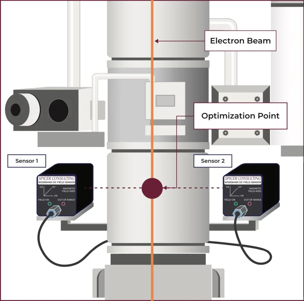
Another benefit of mixing the data from two sensors is that it allows VEC to place the sensors slightly further from the electron beam column. The sensors must detect the ambient magnetic fields, not those generated by the microscope. With only the ability to use one sensor, other vendors often try to place the sensor as close as possible to the column, resulting in contaminated field data from the magnetic lenses and other magnetic field sources on the microscope. The virtual sensor allows the system to optimize cancellation for the center of the electron beam column without being close to other magnetic field sources, which can result in an inaccurate reading of the ambient fields in the room.
Benefit vs. Other Configurations - Hardwired Cancellation Gradients
Other EMI cancellation companies deal with field gradients by hardwiring in a gradient into the magnetic field cancellation loops. Specifically, VEC has seen competitors install cancellation systems with more coils at the top of the microscope than at the bottom if the magnetic field levels are higher at the top of the microscope. By hardwiring more coils at the top of the microscope than at the bottom, competitors create higher cancellation levels at the top of the column than at the bottom. Although this works for stable single-source fields, the setup is static and cannot accommodate changes to field levels over time or fields from multiple sources from different directions.
Dual Cancellation Systems Dynamically Adapt to Changing Field Gradients
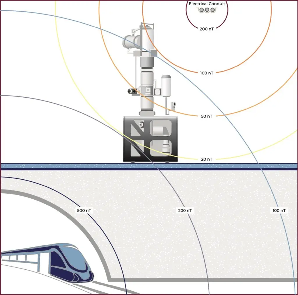
Alternatively, VEC’s Dual Cancellation Systems are dynamic and adapt to changing field gradients from different directions. Suppose our TEM laboratory has AC fields from an overhead electrical conduit and intermittent DC field changes from a subway below. The Dual Cancellation System compensates for the AC fields with a higher field gradient at the top of the microscope and manages the DC field changes from the subway below. It continuously adjusts to cancel both the AC fields and the DC field changes, even with varying gradients from multiple directions.
Integration with Eddy Current Passive Shielding
Even though Dual Cancellation Systems cancel both DC and AC magnetic fields, some customers want to install aluminum eddy current AC magnetic field shielding in their TEM rooms, mainly if the room requires extensive renovation to install the microscope. In these cases, VEC still installs the Dual Cancellation System to protect the TEM from intermittent changes in DC fields and maintain the instrument specification along the entire electron beam column. The integration of the Dual Cancellation System with eddy current passive shielding allows the customer to get many of the benefits of AC passive shielding while protecting the TEM from intermittent DC fields without the cost and schedule implications of DC shielding with mu-metal or other nickel alloy materials.
Meeting the magnetic field specifications for high-resolution TEMs is challenging, especially in laboratories with a high field gradient. The dual cancellation system solves the shortcomings of a single cancellation system layout in TEMs with long columns and tight magnetic field specifications. VEC can install this system as a stand-alone solution or with passive shielding.


